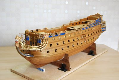
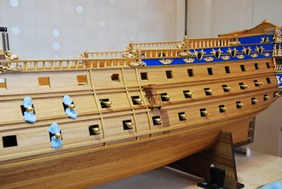
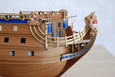
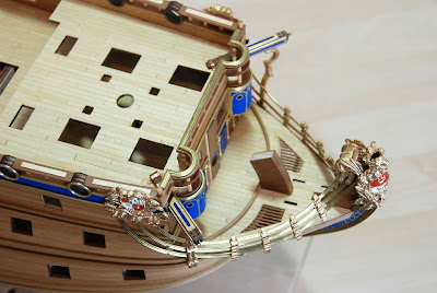
 A general view of the side of the hull with all the chainwales in position. The time for the forseable future is to be spent on the deck fittings. Although there is still plenty to do on the hulls exterior including the gun ports.
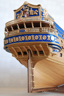
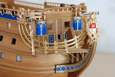
 Another view of the coloumns with the doors and windows in place.

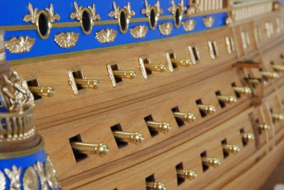
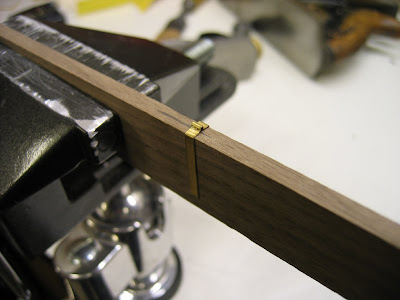
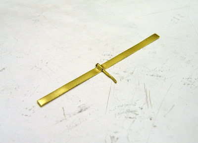
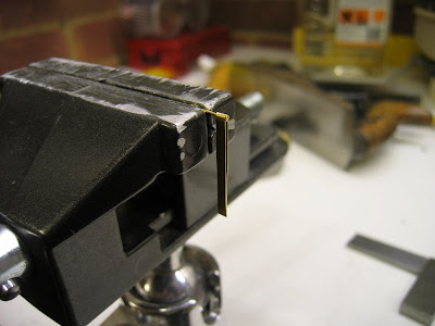
 It was now time to finish the chainwales with the brass support brackets, these were checked for shape and angle and then glued under the chainwales and fixed on the other end with a brass pin to the hull.
 The finished chainwales in position along with the newly cut brackets, I was very pleased with how these worked out.
 The small triangular brakets were made using a CAD drawing, I then routered them out using my CNC router at my work place. Three different types were made each with a varing amount of angle to allow for the curverture of the hull. The correct one was then selected depending on where it was positioned on the hull.


.jpg)
.jpg)
.jpg)
.jpg)
.jpg)




.jpg)
.jpg)
.jpg)
.jpg)


.jpg)
.jpg)
.jpg)
.jpg)
.jpg)


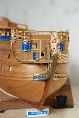
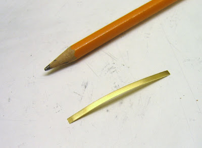
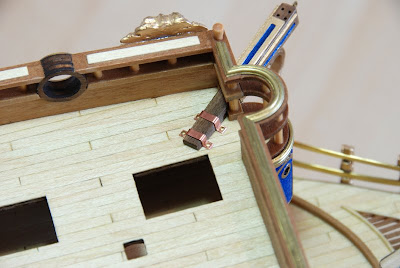
 That was the easy bit, it now had to be bent in the other direction, I found it also had a twist at either end. This really was trial and error to get it looking right. After about 2 evenings worth of work 1 was finally ready to fix to the hull, just 5 more to do then !
